Interactive Radio
The idea of this project was to create a working radio, that creates a new paradigm of interaction. Unfortunately, this is a realm of design which is typically neglected in today’s consumer products. In addition to this however, from my own experience, the experience of others, and several books, I have found that the best design is also one that marries form and function as well. After all, this helps tell users what the device is, and generally how it should be used. Therefore, this project was an exercise to fulfill these three portions of design, incorporating them together successfully into a final working prototype.
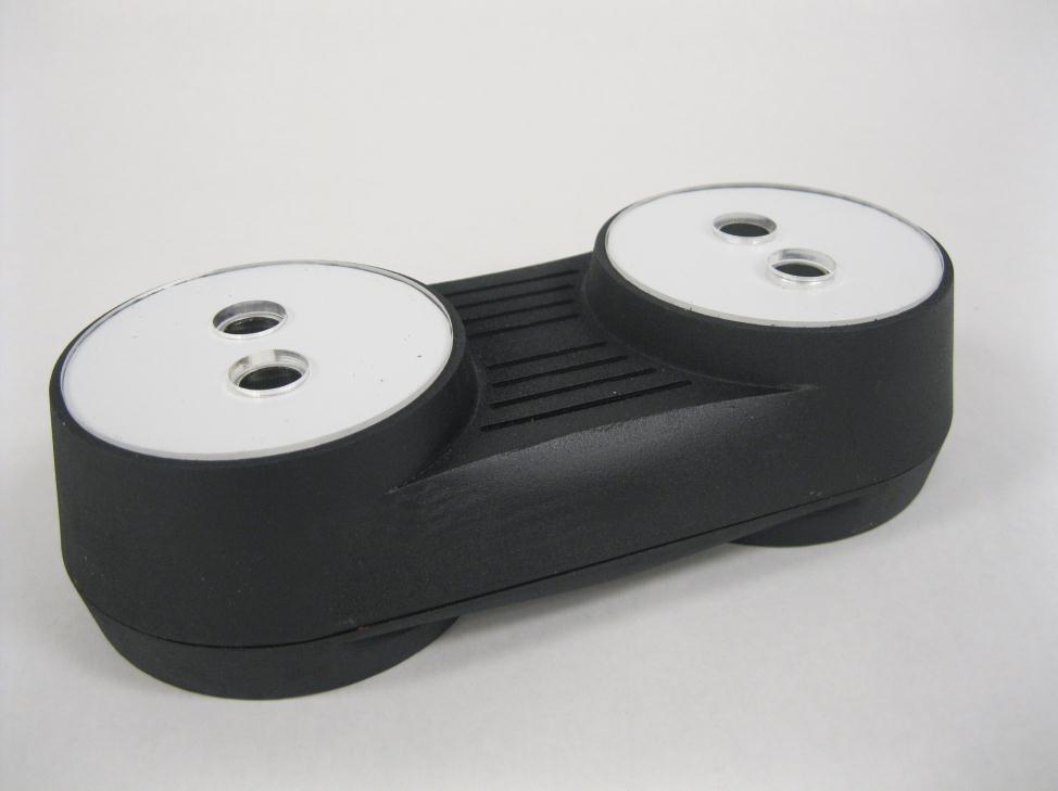
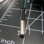
In this project i created a design that allows users to logically correlate their actions, with the radio effects outcome. For example, it is natural to associate an increasing volume with increasing hand height, as well as increasing and decreasing radio frequencies with a similar increasing and decreasing hand motion. With that in mind, I built this radio to read hand gestures using sonar, while incorporating a form that suggests the user should place their hands over the white circular platforms to control the radio. With this in mind, the following procedure generated the final concept illustrated above.
Because I had limited radio construction experience, my first step was to become familiar with how a radio works, and how to control it–aka, take one apart and tinker with it! Therefore, my new goal was to create a simple ‘foam core radio prototype’ using the components of a pre-existing radio. To determine what I wanted my foam core radio to accomplish, I created some initial brainstorm sketches.
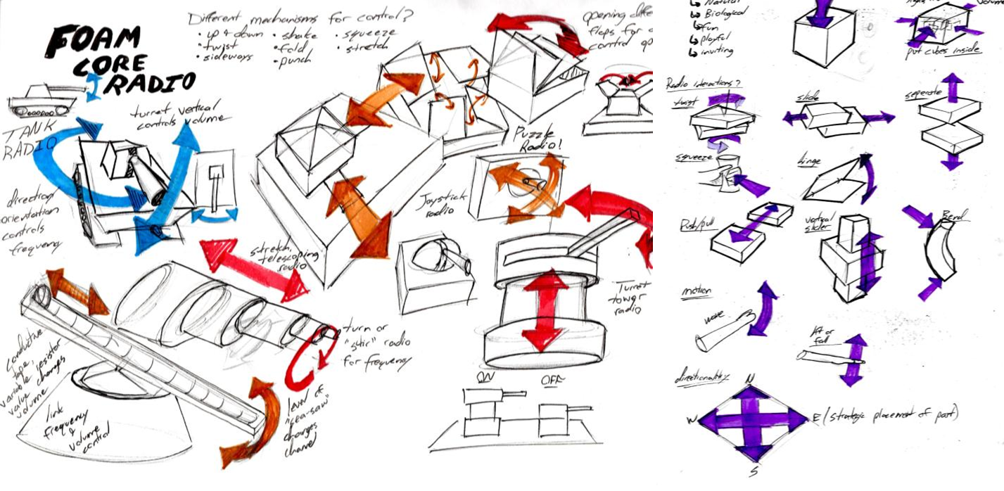
After sketching several concepts, I decided to create an initial ‘tank prototype’ foam core radio–with simplified forms to expedite the process. The following picture sequence illustrates this process.
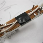
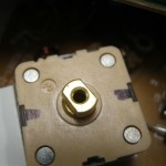
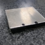
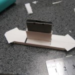
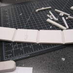
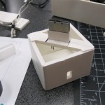
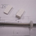
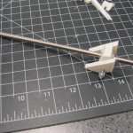
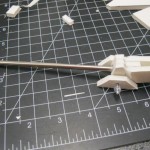
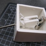
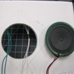
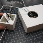
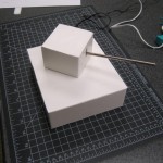
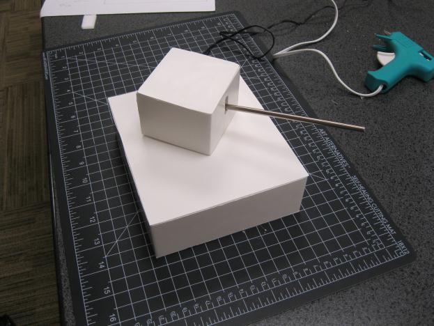
As the process pictures above show, I used a slide potentiometer to link the silver lever’s ‘up-down’ motion with volume, and also mechanically linked the rotating turret with the radio’s provided rotational potentiometer to control the frequency. I also glued a gravity switch to the silver lever inside the turret so when the user wanted to turn the radio off, they simply lowered the volume until the radio was turned off.
Now that I had more experience tinkering with radios, I set off to design my own. Once again, I began with some concept sketching.
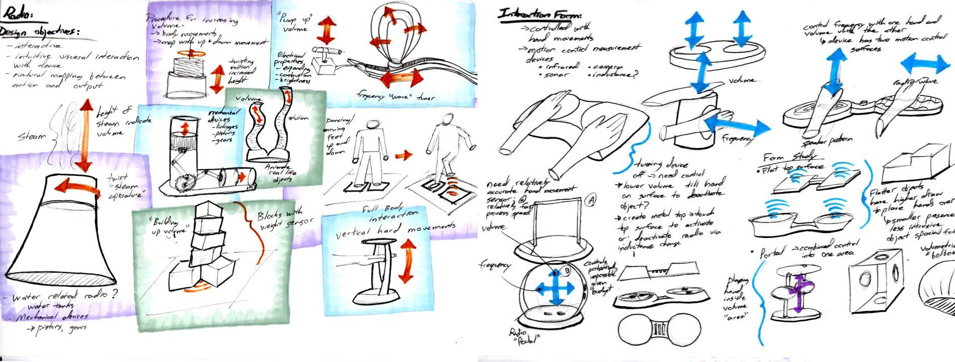
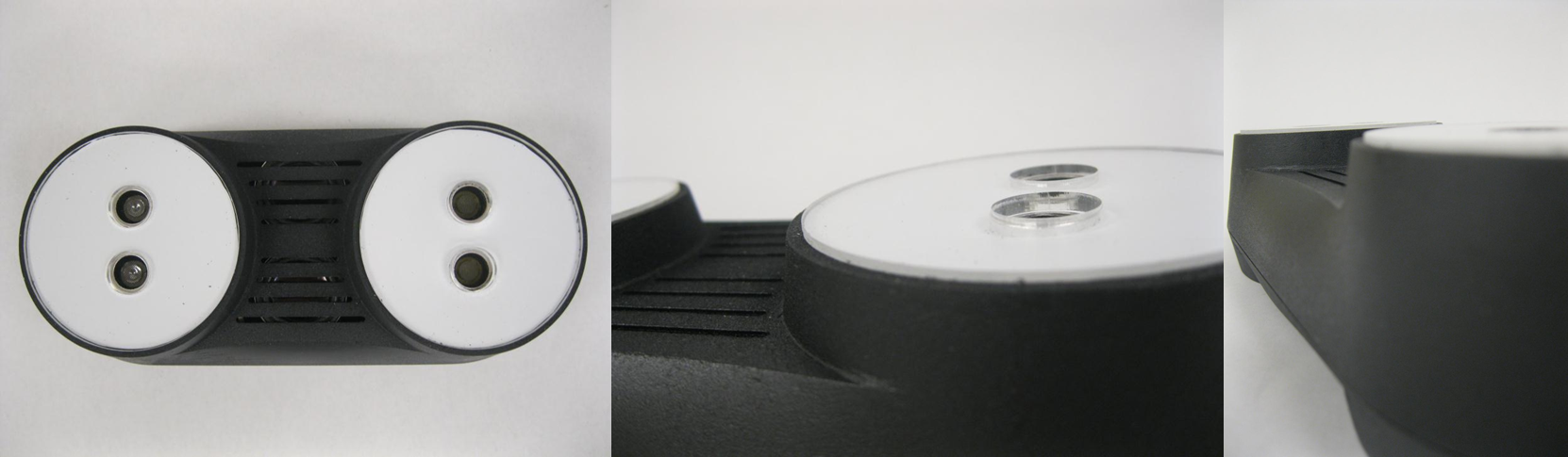
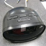
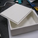
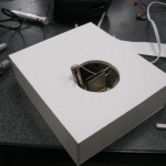
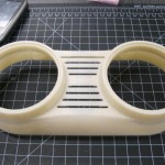
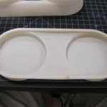
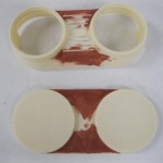
After some deliberation I chose to pursue a motion sensing radio interface. This would allow the user to control the volume with one hand’s motion, and the radio frequency with the other. The radio would incorporate a flat ‘drum’ like form to encourage the user to naturally place their hands over the two large circular control faces. The left circle would control the volume, while the right would control frequency. To explore the effectiveness of the chosen form, I began creating a foam core prototype for use in user research.
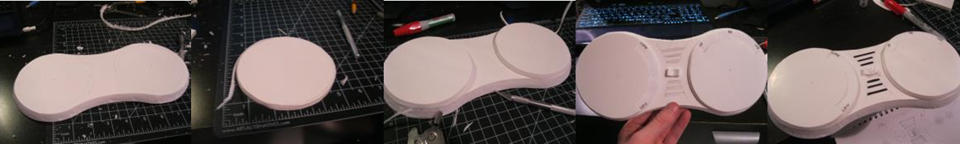
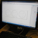
Using the prototype constructed above, I found a majority of users presented with the prototype form place their hands over the pads relatively quickly during their initial ‘exploratory phase’ with the model. I also found users were initially confused with what the central on-off switch was portraying. It generally added an unnecessary level of complexity to the design, so I decided to get rid of it entirely. The user would simply activate the device when their hands were sensed over the control surfaces. Armed with these new findings, I started a CAD design using SolidWorks.
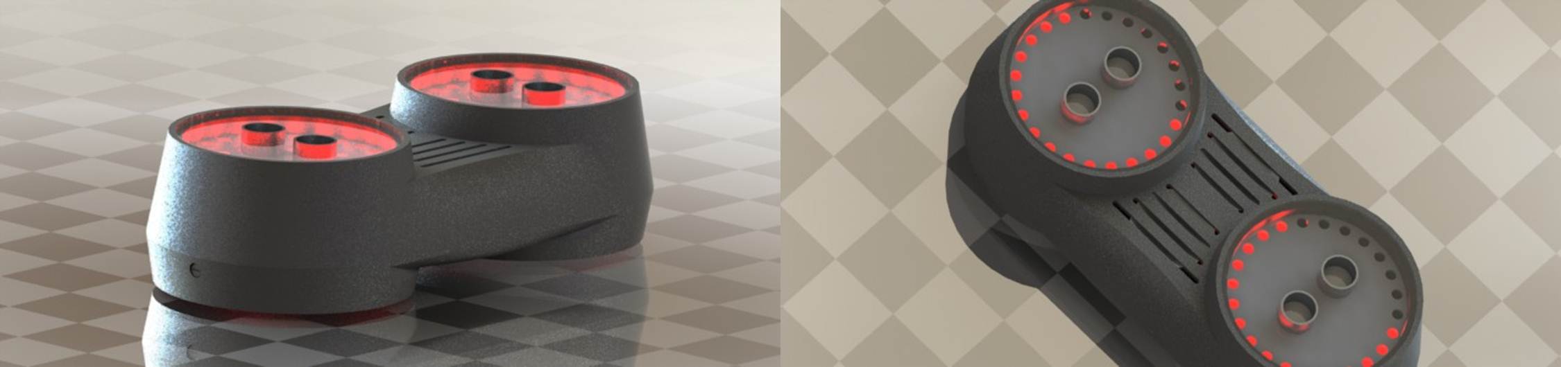
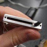
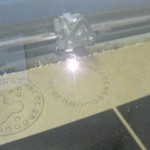
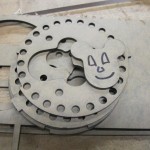
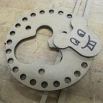
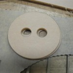
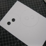
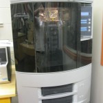
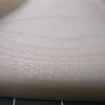
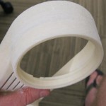
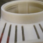
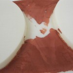
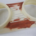
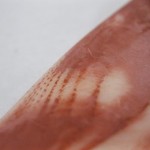
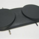
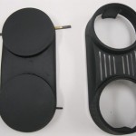
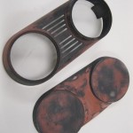
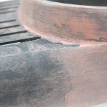
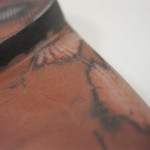
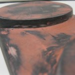
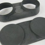
Once I had the CAD model completed, I began the fabrication process using both a 3D printer to print the radio shell with ABS plastic, and a laser printer to cut out the flat control surfaces to fit inside the plastic shell. Because the plastic form was still rough, there was also a long iterative string of puttying and sanding to produced a part with a smooth finish. At which point several coats of fresh paint produced a show quality finished part. The process is illustrated below.

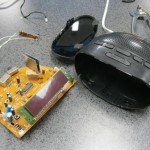
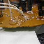
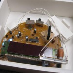
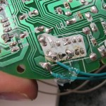
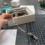
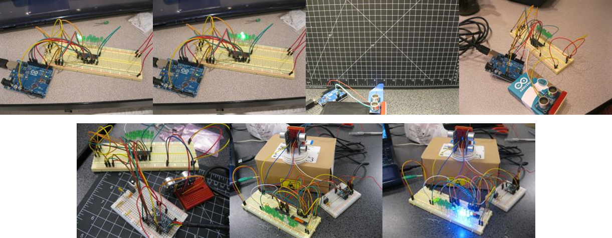
The next step was completing the electronics. My first step was to create a working electrical prototype, which I successfully completed as illustrated below.
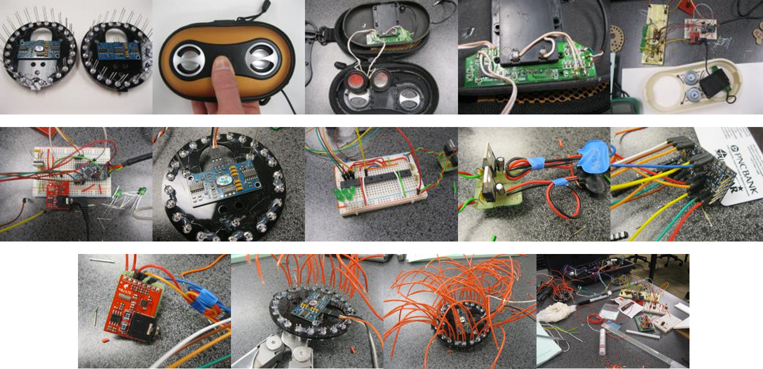
After this prototype, the next challenge was packaging all the electronics. After trying to manually solder all the volume/frequency LED indicator leads to each respective multiplexer output with individual wires, I quickly realized there would not be enough room for the mass of wires plus the batteries. And, as it always is, timing was knocking down the front door demanding results, so I didn’t have time to design and order a PCB to solder each LED onto in an orderly fashion, like I should have been doing in the first place.
However with every defeat comes a valuable lesson. In this case, I was reminded that although overall form, user interface, and user interaction are all useful elements to explore in the mission of increasing product value, the bread and butter engineering parts also demand equal priority towards achieving product success. I should have made time inside my development schedule for an in-depth electrical component packaging analysis, taking place concurrently with my my stage III CAD work. This would have alerted me of the electrical component size requirements, thereby directing me to design and order a space saving PCB for the LED indicators.
This experience just further stresses the importance of a fluid marriage between engineering and design — because only then can an innovative consumer valued product be brought to life.
Copyright © Scott Fisher
Leave a Reply